
Laser Shearography for Advanced Composite Testing
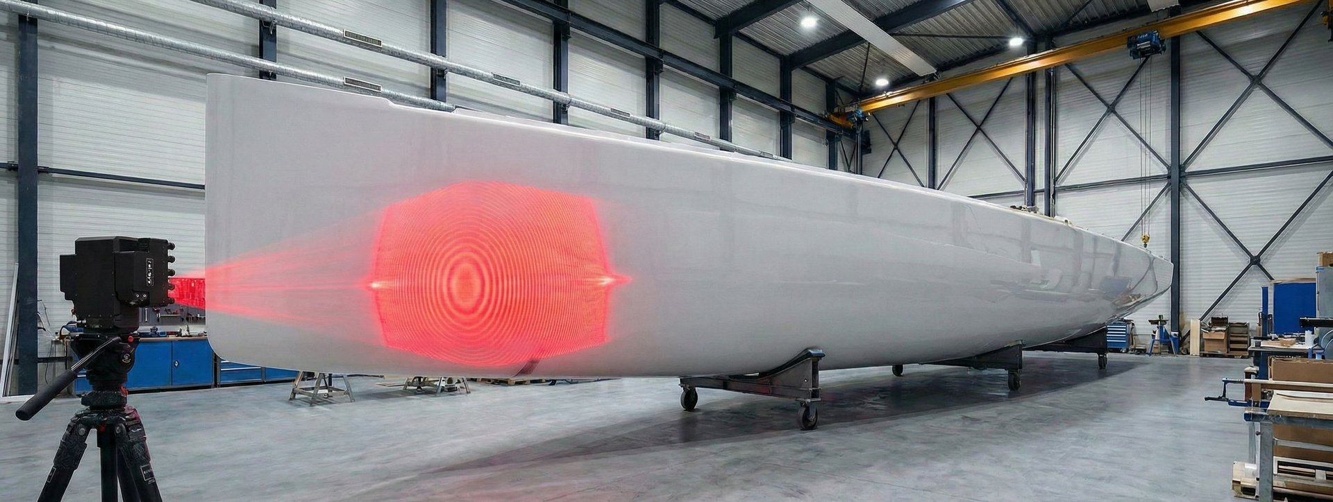
Shearography does not see defects directly. It sees how the structure deforms under load. If a flaw changes the local stiffness or deformation response, it can be revealed without contact and without damaging the part.
/ Measurement Principle
Deformation under load is the signal
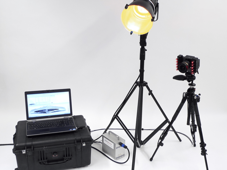
Laser shearography illuminates a surface with coherent light and compares phase before and after a controlled load is applied. Subsurface defects such as delaminations, disbonds and voids produce a local anomaly in the deformation field that the system maps across the full inspection area simultaneously.
The method is non-contact and non-damaging. It does not replace ultrasonic or thermographic inspection, it is most effective where a structural discontinuity creates a detectable deformation response under the loading condition you apply.
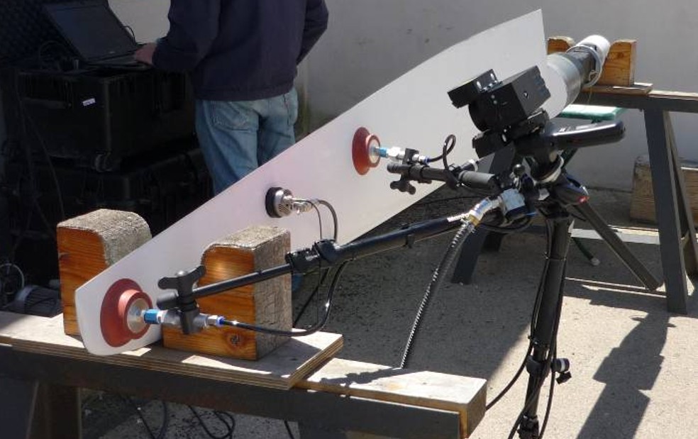
In the adjacent clip, you can see lamb waves being generated in the test object (lower part) by a piezo shaker that then shows five subsurface defects (top part).
/ Powerful, yet simple software
isi-Studio Butterfly for Shearography
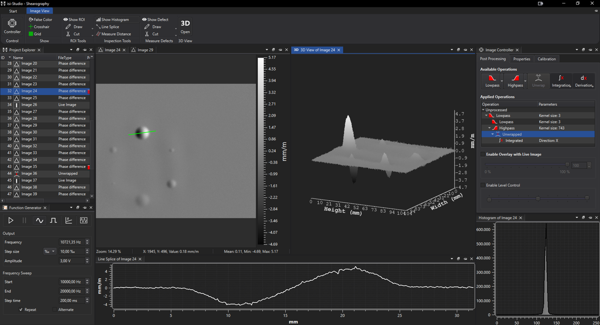
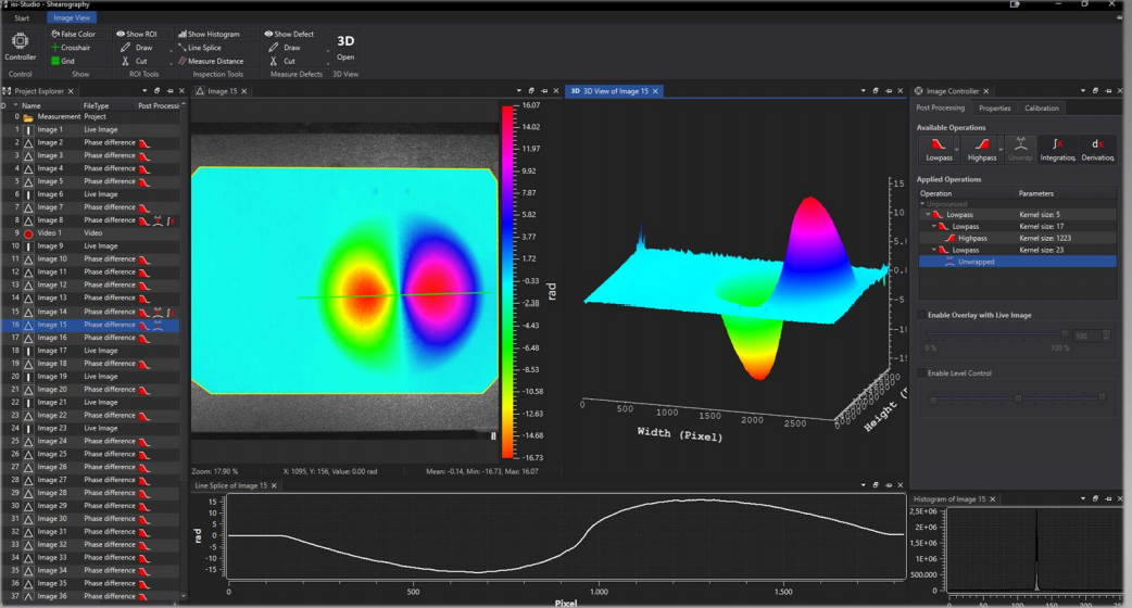
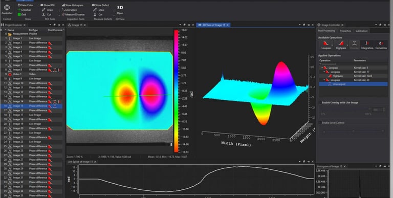
isi-Studio Butterfly is the software platform for SE4 shearography inspection, combining hardware control, image capture, phase reconstruction, filtering, defect evaluation and reporting support in one workflow.
The software controls connected inspection hardware directly from the interface, including cameras, triggering, lighting, vacuum equipment and dynamic loading devices. This helps operators run controlled, repeatable inspections instead of relying on disconnected tools and manual settings.
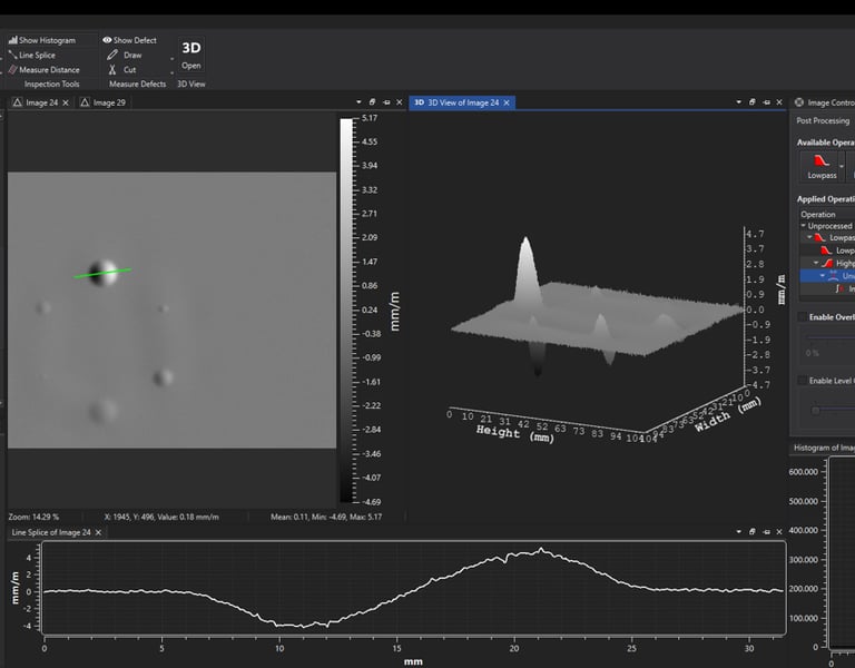
For evaluation, isi-Studio Butterfly supports real-time phase reconstruction, digital filtering, automatic image scaling, shear distance determination, exposure adjustment and defect measurement tools. Operators can review live and post-processed images using histogram, line-splice and 3D visualisation tools.
For suitable applications, AI-assisted defect recognition can help operators evaluate shearography results faster and more consistently. The clip below shows rear thermal loading of the test object, with the software view embedded at the top right automatically marking defect indications in red boxes for review.
\ Application-Specific Loading
Defect detection starts with the correct excitation method
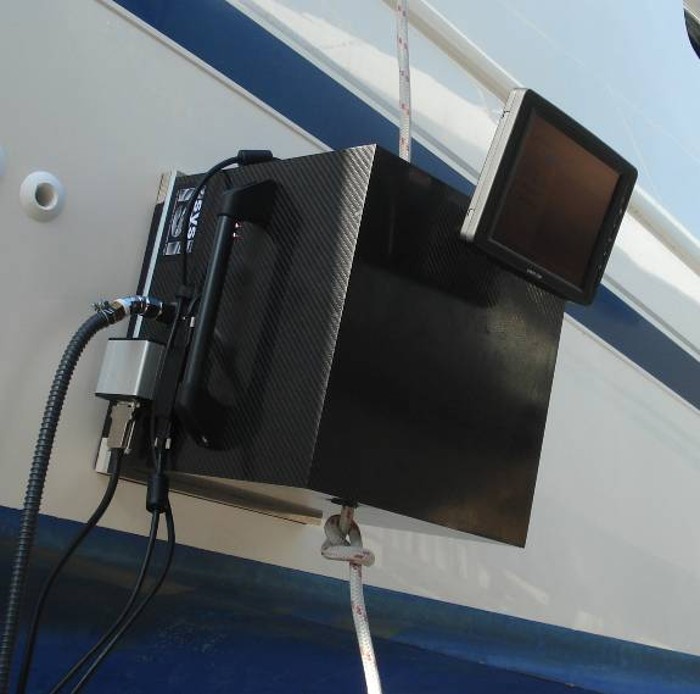
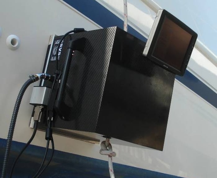
Shearography is most effective when the loading method is matched to the structure and the defect mechanism. ACS supports the selection of thermal, vacuum, pressure, dynamic or mechanical loading to produce reliable, repeatable inspection results.
Thermal loading
Vacuum loading
Controlled surface heating creates small deformation differences around hidden defects. Well suited to delaminations, disbonds, impact damage and skin-to-core defects in carbon fibre and sandwich composite structures.
A vacuum hood applies a controlled pressure differential across the inspection area. This can reveal weak bonds, disbonds and skin-to-core separations in sandwich panels, bonded repairs and accessible composite surfaces.
Vibration and dynamic loading
Pressure loading
Mechanical or acoustic excitation introduces a controlled dynamic response into the structure. This can reveal disbonds, delaminations and local stiffness changes, especially in bonded assemblies, composite panels and components where defects respond at particular excitation frequencies.
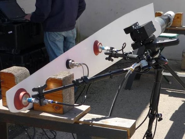
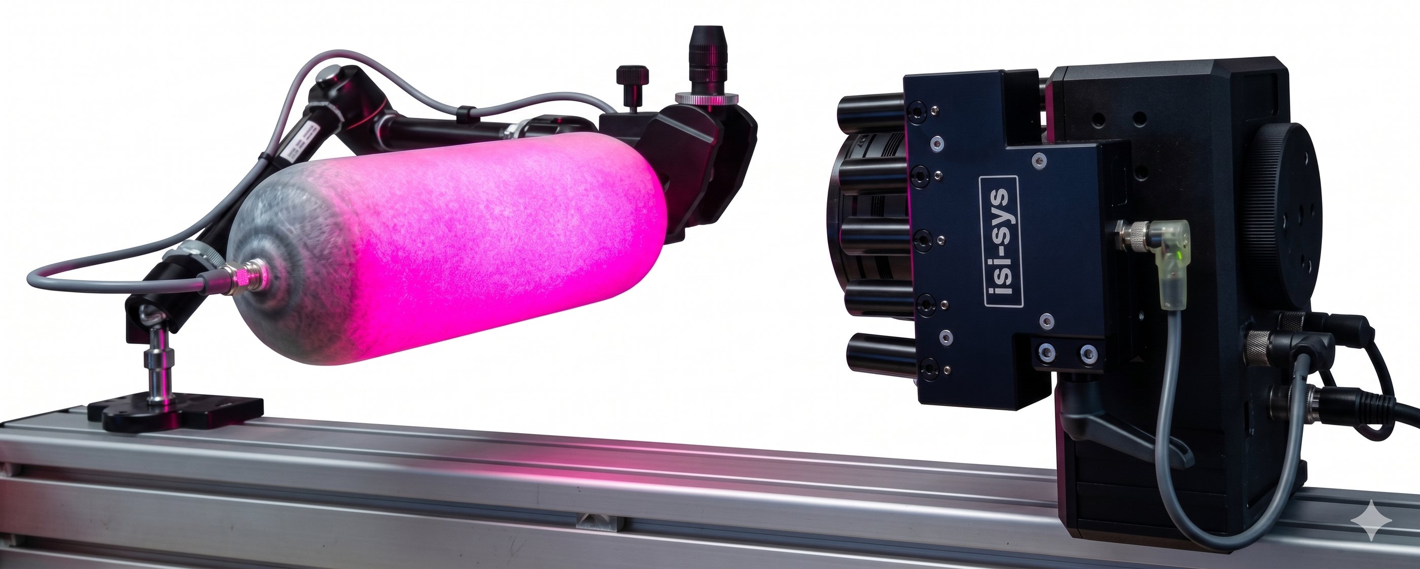
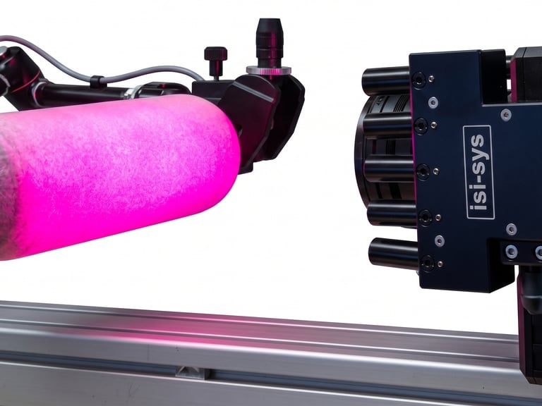
Tubes, cylinders and pressure vessels can be internally pressurised to create a controlled deformation response. Shearography highlights local stiffness changes, disbonds, delaminations and structural defects that respond differently from sound material.